| 5mm Flex |
|
|
|
|
|
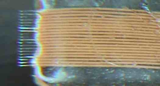
Back To Embedded Info Page I recently got a sample of a graphics LCD display module that is a Chip on Glass (COG) type module. Displays of this type typically have a fine pitch flex cable attached at the LCD glass that then normally connects to a corresponding fine pitch flex connector on the host PC board. I was very anxious to try out the display and see how it looked with a sample display showing on it. Since this display is targeted for use in a customers product I wanted to prototype the setup to an 8051 style microcontroller. This would allow me to reuse any of the code I wrote for the prototype process in the eventual product environment. On this page I show how I dealt with connecting the flex print cable from the display to an 8051 evaluation board. Note that the flex print cable was very fine pitch with leads on 0.5 mm centers. Here is a picture of the 106 by 56 pixel display module. Note the flex cable.  I did some searching on the WEB to check on the availability of some type of adapter that would permit me to easily connect the display to the evaluation board. I found one adapter here, but it was in Germany and my being in the US made it seem as an expensive solution to the connection problem -- not to mention the time delay to get it. Thus I set out to find a quick connect solution. I purchased a suitable connector for the flex cable from DigiKey but it became obvious right away that all available 0.5 mm pitch flex connectors were surface mount parts. It turns out to be extremely difficult to solder individual wires to a surface mount connector so I fabricated a kind of harness of 20 parallel wires. This harness was made by attaching a piece of clear tape to the edge of my work table with the glue side up using two other pieces on the ends. The tape was used to hold twenty (20) pieces of wire that were cut and stripped in careful parallel registration. The wire was 30 gauge wire-wrap wire with Kynar insulation. It is important to select the proper wire. I found that one type with an outside insulation diameter of 0.53 mm was too wide for my goal of 0.5 mm center to center spacing. The wire I actually used was 0.47 mm in outside diameter and worked out quite well. The picture below shows the first few wires placed on the tape.  After all the wires were firmly stuck in place I mixed a small batch of quick setting  5 Minute Epoxy and put a small rectangle of it over the top of the wires and just up to the stripped ends. After that had set I peeled all the tape away and turned the assembly over and applied a second batch or the epoxy on to the opposite side of the wires. The following picture shows the harness clamped in place on the bench while the epoxy on the second side was hardening. 5 Minute Epoxy and put a small rectangle of it over the top of the wires and just up to the stripped ends. After that had set I peeled all the tape away and turned the assembly over and applied a second batch or the epoxy on to the opposite side of the wires. The following picture shows the harness clamped in place on the bench while the epoxy on the second side was hardening. The stripped wire ends of the glued harness assembly were then trimmed to a length of about 2.5 mm. The ends were then carefully aligned so that they were evenly spaced and in the same flat plane. The picture here is an image of the harness taken under a magnifier so that you can see the trimmed result. The goal is to use this assembly as a unit and to attach it to the lead ends of the purchased connector similar to the process of soldering the connector to pads on a PC board.  I ended up purchasing a vertical type of flex print connector. A picture of it is shown below. The OMRON part number for this one is XF2J-2024-11. I selected this connector because the parts of the leads that normally attach to a PC board are designed so they extend beyond the connector body. All the odd numbered pins extend out one side and the even numbered one stick out the other side. (This is normally meant to provide stability of the connector on the PC board). I intended to take advantage of this because this makes the center to center of the lead tips be 1.0 mm on centers on each side.  Next I prepared the wires on the end of my harness assembly as shown in the drawing below. (Sorry about the Autocad sketch of this as opposed to a real picture but I thought the drawing makes the lead formation much more clear). With the leads bent in this manner I was able to then place the OMRON connector directly in from the end and solder each wire end to one of the tips of the contacts on the connector.  Finally I was able to attach a standard 2.54 mm on centers 2x10 connector on the opposite end of the harness. The whole assembly was then potted from connector to connector with more of the Devcon epoxy. I used pieces of the type of plastic used in clear blister packs from the store that were taped together to make the mold for the epoxy. This type of plastic does not readly adhere to the epoxy and can be easly removed after the glue has set. The final result of the assembly is shown in the following two pictures. As you can see it is now very easy to adapt the 2x10 connector with a short ribbon cable to the prototype area on a SiLabs 8051 type evaluation board.    |
|
|
|
|
Email:
mkaras@carousel-design.com
Web Site: www.carousel-design.com |

|