 |
gLCD Software
|
Using Bitmapped Fonts With a Graphics LCD Module
Back To Embedded Info Page
Note: This page has been updated with improved code and new code samples for several additional display types. Updated 16 Mar 2003.
I recently started work with a graphics LCD module that is a
Chip on Glass (COG) type module. I had spent a fair amount of time searching on
the Internet for software drivers to interface an 8051/8052 type processor to a
display of this kind. I was rather surprised to find that there is very little
freeware of a type suitable for the needs of a typical embedded systems
design....so I made it a goal to develop a graphics LCD library with included
bitmap font support. This page is a presentation of the results of that work
and provides a link where avid 8052.com visitors can access a free download of
this software.
Here is a quick look at the nice types of fonts that can be
displayed on a graphics LCD module. These pictures should certainly get some
readers interested in the use of graphics LCD modules as opposed to the fixed
character mode displays of days done by. I suspect that many 8051/8052 system
designers would like to use a graphic display on their microcontroller but are
held back by the learning curve and implementation hurdle. Well that need not
be a problem any longer!!
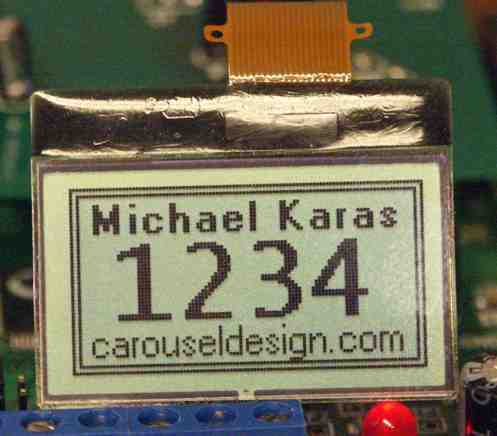 (Click on image above to see a bigger version).
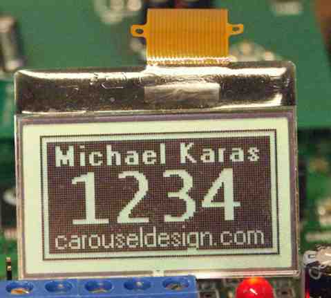 (Click on image above to see a bigger version).
I decided to use an off the shelf development board to host
the creation of the software. Readers of my pages here will know that I am a
fan of the 8051 derivative microcontrollers from Silicon Labs so it should be no
surprise that I chose to use a low cost board with the Silicon Labs C8051F020
processor. This processor is a device with 64K of FLASH program memory and 4K
bytes of XRAM resident on the chip. The development board is setup with a
22.1184 MHz crystal and with the Cygnal 1X clock divide ratio the board
provides good code execution performance. The board comes with connectors for
power, the Cygnal JTAG download/debug cable, a 96-pin DIN connector that
provides access for almost all processor pins and headers for each of the 8
ports. There is even an RS232 port connector on this board so it is easy to
connect it to your PC or other serial device.
Here is a picture of the Silicon Labs evaluation board with a link
for C8051F020DK
Information at the Silicon Labs Web Site.
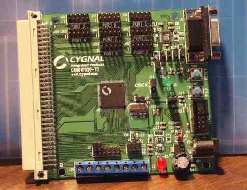
The display I used for this project is a small Chip On Glass
(COG) type from TIANMA. This display is organized as a 106 x 56 pixel array. The
controller IC mounted on the glass is a Samsung S6B0724 that is interfaced to a
fine pitch 20 way flex cable. The logical interface to the flex cable is
provided by connecting the flex cable directly to port pins of the
microcontroller and using software to implement the serial communications to
the controller. Here are links to reference information about the controller
chip and the display module.
S6B0724A
Controller General Description
S6B0724A
Controller Data Sheet
TIANMA
Display Picture
TIANMA 106 x 56 Display
Drawing
At first I messed around with this display using a quick
adapter that I fabricated so that I could attach it to the microcontroller
development board. You can see pictures of that work here. More recently I made a small PC board
adapter to directly connect the display to the Silicon Labs C8051F020 development
board. Here is a picture of that adapter that also shows the TIANMA display
module. Note that the adapter shown has two sites for connecting LCD modules
from different manufacturers. The TIANMA connects to the lower one in the
picture.
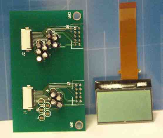
A schematic diagram of the adapter is shown below. This will
show how the 20 signals of the flex cable are connected to the microcontroller.
Note in particular the group of capacitors that are used by a charge pump on
the S6B0724 chip to boost the VDD of 3.3 volts up to the 9 -> 10
volts required as a bias for the LCD glass.
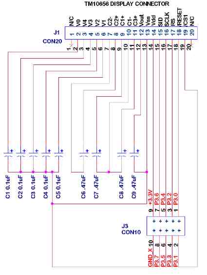 (Click on image above to see higher resolution
schematic).
To develop the software I used the Keil C51 C language
compiler installed with the Silicon Labs IDE. This provided me a very nice
development environment due to the source level debugging offered by the Silicon Labs
IDE when used in conjunction with the JTAG debug hardware support that is built
into all Silicon Labs processors. Here is a picture of the complete development
setup. Notice the small adapter device on the right side of the picture. This
device converts the RS232 port of the development PC to the JTAG signals needed
by the Silicon Labs microcontroller.
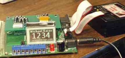
The code I developed for this project was designed with the
S6B0724 display controller in mind, but the code can be used with the display
controllers on other LCD modules as well. There are several graphic display
controllers from other manufacturers that operate almost identical to the
S6B0724 chip. In addition there are other chips that implement the LCD control
function is a slightly different way, but the code I developed can be adapted
to these other display controllers without too much work. The main concerns
when working with graphics modules are:
- Orientation
of the data bytes in controller to the horizontal or vertical direction.
- Orientation
of the rasters of the data bytes in the bitmapped font data.
- Order
of the bits of the within the byte in controller such as if D0 is to
top/left or to the bottom/right.
The diagram below shows the layout that is specific the S6B0724 controller chip.
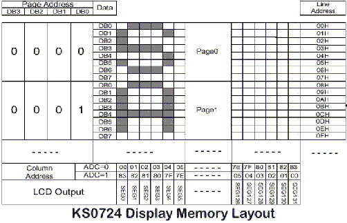
The LCD graphics functions are coded into a single C source
file along with a companion header file that exports all the significant
function names and defined constants for use in other source files. The
developed code includes the following list of functions:
    void lcd_init(void);
    void lcd_out_dat(char dat);
    void lcd_out_ctl(char dat);
    void lcd_erase(void);
    void lcd_test(unsigned char pattern);
    void lcd_clear_area(unsigned char left, unsigned char top,
                        unsigned char right, unsigned char bottom);
    void lcd_invert_area(unsigned char left, unsigned char top,
                         unsigned char right, unsigned char bottom);
    void lcd_horz_line(unsigned char left, unsigned char right,
                       unsigned char row);
    void lcd_vert_line(unsigned char top, unsigned char bottom,
                       unsigned char column);
    void lcd_clr_horz_line(unsigned char left, unsigned char right,
                           unsigned char row);
    void lcd_clr_vert_line(unsigned char top, unsigned char bottom,
                           unsigned char column);
    void lcd_box(unsigned char left, unsigned char top,
                 unsigned char right, unsigned char bottom);
    void lcd_clr_box(unsigned char left, unsigned char top,
                     unsigned char right, unsigned char bottom);
    void lcd_glyph(unsigned char left, unsigned char top,
                   unsigned char width, unsigned char height,
                   unsigned char *glyph, unsigned char store_width);
    void lcd_text(unsigned char left, unsigned char top,
                  unsigned char font, char *str);
    void lcd_update(unsigned char top, unsigned char bottom);
I have organized the
font handling in this code so that bitmaps for the font are compiled into the
FLASH code space of the microcontroller as constant data. The bitmap data for
the fonts was created as C source code using the FontGen utility created by a
clever gentleman named Bahri Okuroglu. You can read about FontGen and access a
download link at his FontGen
Web Page. Each font that is "sourced" by FontGen uses a
definition structure of the format shown below:
    struct FONT_DEF
    {
        unsigned char store_width;        /* glyph storage width in bytes */
        unsigned char glyph_height;       /* glyph height for storage */
        unsigned char code *glyph_table;  /* font table start address in memory */
        unsigned char fixed_width;        /* fixed width of glyphs. If zero */
                                          /* then use the width table. */
        unsigned char code *width_table;  /* variable width table start address */
    }
I have organized the font file in the developed source code
so that it contains an array of these FONT_DEF structures. Then the text
display routines can simply reference the font typefaces by font number. For
example the code I wrote has three fonts installed as "normal",
"bold", and "bigbold" that are referred to fonts 0, 1, and
2 respectively. Here is the code that shows this array of the structures:.
    /* definition tables for three fonts as follows:                             */
    /* all fonts include 96 glyphs from 0x20 to 0x7F that are in ASCII order     */
    /*                                                                           */
    /* Font #0: normal_font - a light variable width font that is 13 pixels high */
    /* Font #1: bold_font - a heavy variable width font that is 13 pixels high   */
    /* Font #2: bigbold_font - a large fixed width font that is 32 pixels high   */
    /*                                                                           */
    struct FONT_DEF code fonts[] =
               {
                {2, 13, normal_glyph_table, 0, normal_width_table},    /* normal */
                {2, 13, bold_glyph_table, 0, bold_width_table},          /* bold */
                {3, 32, bigbold_glyph_table, 20, NULL},               /* bigbold */
               };
As you can see from
the table above the fonts can be fixed width or variable width. Variable width
fonts have an indirectly referenced table that provides the widths for each of
the glyphs in the font set. Note that these tables are also built by Bahri
Okuroglu's FontGen program.
The bitmapped font rendering
code that I wrote uses a concept of a screen image array kept in the processor
memory space that is then copied out to the LCD controller as needed. This is
an efficient method to implement a graphics LCD driver for two reasons. First
off it is far more convenient to be able to read the existing pixel image data
from the memory array when it is necessary to insert new pixels into a
partially modified byte as opposed to trying to read them back out of the LCD
controller chip. Secondly the common COG style LCD modules often are setup to
use a serial interface as opposed to a parallel interface. This is nice in that
it makes the flex cable narrower but, as in the case of the S6B0724 controller
chip, it also leaves the internal ram in the controller accessible in a write
only manner. (i.e. the serial interface is unidirectional). Another
consideration is that it is possible to write a very tight and efficient
routine to copy this memory buffer to the display controller because of the
fact that graphics LCD controllers permit you to set the address within a
memory page once and then you can simply transfer the bytes for the page by a
sequence of data register writes and the internal address auto increments. The
106x56 display I used has 7 pages of display memory so the whole screen can be
updated by setting the page/column address 7 times and squirting out 106 bytes
of data to each page. The total size of the memory buffer for the 106x56
display is 742 bytes. This buffer was placed in the on-board XRAM space of the
Silicon Labs C8051F020 processor where it used less than 25% of the available 4K byte
memory. The modern processors of this type that have this onboard XRAM make
embedded products with graphic LCD modules possible without having to design in
a separate memory chip. A real common type of graphics module is the 128x64
pixel size. These require a 1024 byte buffer.
The code to display
the screen images shown at the beginning of this web page is shown below. As
you can see it is very easy once the font bitmap and the LCD interface and font
rendering code is in place. Note in particular that the display is changed via
the various calls in the LCD code set to draw lines, boxes, cleared areas,
inverted areas, and bitmap font data. These calls simply draw pixels into the
internal image buffer. Once the software has "painted" the new image
a call to the lcd_update() routine is made to cause the actual display
to be updated from the memory image buffer. Notice that this routine has entry
arguments that permit just a portion of the display to be updated. This feature
is provided to increase performance in instances where software is updating
only a small area on the screen.
sbit SWT = P3^7;

void main (void)
{
    config(); // setup all the SFR initialization
    lcd_init()   // initialize LCD display
    lcd_erase();   // erase the display

    while(1)
    {
        // switch over to the buffered interface
        lcd_clear_area(SCRN_LEFT,SCRN_TOP,SCRN_RIGHT,SCRN_BOTTOM);
        lcd_box(SCRN_LEFT,SCRN_TOP,SCRN_RIGHT,SCRN_BOTTOM);
        lcd_box(SCRN_LEFT+2,SCRN_TOP+2,SCRN_RIGHT-2,SCRN_BOTTOM-2);

        lcd_text(6,3,1,"Michael Karas");
        lcd_text(11,15,2,"1234");
        lcd_text(5,40,0,"carousel-design.com");
        lcd_update(SCRN_TOP,SCRN_BOTTOM);

        while(SWT == 1);
        while(SWT == 0);

        lcd_invert_area(SCRN_LEFT+2,SCRN_TOP+2,SCRN_RIGHT-2,SCRN_BOTTOM-2);
        lcd_update(SCRN_TOP,SCRN_BOTTOM);
        while(SWT == 1);
        while(SWT == 0);
	}
}
I have gathered the
code for this project into a ZIP file that you are free to download and use as
you wish. The code provided is all written in C language and compiled using the
Keil C51 compiler. The code is small enough that it should be possible to
compile it with the evaluation version of the Keil compiler that comes with the
Silicon Labs development board. (That version is limited to 4K of code. The
download version from the Keil web site is limited to 2K of code). However
it will most likely be necessary to strip out two of the fonts. There is no
reason that this code cannot be compiled with other C compilers and targeted to
other types of microcontrollers as well. There would be only minor changes to
the code required to port in this manner.
If you download this
code and use it in a project I would request that you send me an email of how you used the gLCDcode
Download gLCDcode
(Please note that
I am providing this code "as-is" and it is up to you to determine its
usefulness for your application. As such you assume all responsibility for its
use and application. I cannot provide free technical support to help you get it
working for your controller or hardware setup. However if you have a minor question
of how some portion of the code works or why it was written in a particular way
please feel free to send me a question via email. I will try to answer all
questions but cannot guarantee this as I get tons of email and I also run a
consulting business to earn a living and that has to come first. You can also
email if you want support on a consulting basis. There is a link above with my
email address).
UPDATE SECTION
I have done some additional work to the gLCD code that is now available for
download. The new code sets are an update to the original download package,
which is still available above. The updates to be found in all of the new code
sets include several bug fixes in the font glyph painter routine, a new feature
of the lcd_text() routine that causes it to clip any text that extends beyond
the edge of the screen, and support for fonts that do not consist of the
complete ASCII 0x20-0x7E character range. There are three different download
sets available for different sized displays. In one case the supported display
uses a different LCD module controller.
* * * * *
gLCD for Tianma 106x56 Display with S6B0724 Controller
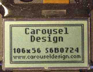 (Click on image above to see a bigger version).
 (Click on image above to see a bigger version).
This 106x56 pixel display is the same display module
discussed above in the main project page. The display is mapped to the memory
buffer bytes such that the bits in a specific byte are shown on the display as
8 vertical dots. Bands of these bytes called “pages” make up eight pixel high
stripes across the display. The S6B0742 controller can be used on displays up
to 132x65 and it is necessary to program certain chip registers in a special
manner to map the display in a way that makes it fast and efficient to update
the display. One example of this mapping that has to be done is to start the
loading of the screen image at column 26 for the left edge of the screen.
Download gLCD106x56.zip
(Please note that
I am providing this code "as-is" and it is up to you to determine its
usefulness for your application. As such you assume all responsibility for its
use and application. I cannot provide free technical support to help you get it
working for your controller or hardware setup. However if you have a minor question
of how some portion of the code works or why it was written in a particular way
please feel free to send me a question via email. I will try to answer all
questions but cannot guarantee this as I get tons of email and I also run a
consulting business to earn a living and that has to come first. You can also
email if you want support on a consulting basis. There is a link above with my
email address).
* * * * *
gLCD for Tianma 128x64 Display with S6B0724 Controller
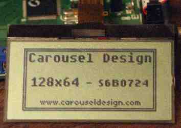 (Click on image above to see a bigger version).
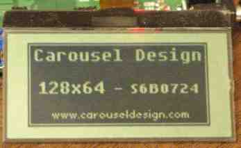 (Click on image above to see a bigger version).
This 128x64 pixel display is a similar module from
Tianma that is connected to the Silicon Labs development board in exactly the same
manner as the smaller display discussed above in the main project page. This display is mapped to the memory buffer bytes such that the bits in a specific byte are shown on the display as
8 vertical dots. Bands of these bytes called “pages” make up eight pixel high
stripes across the display. The S6B0742 controller can be used on displays up
to 132x65 and it is necessary to program certain chip registers in a special
manner to map the display in a way that makes it fast and efficient to update
the display. One example of this mapping that has to be done is to start the
loading of the screen image at column 4 for the left edge of the screen.
Download gLCD128x64.zip
(Please note that
I am providing this code "as-is" and it is up to you to determine its
usefulness for your application. As such you assume all responsibility for its
use and application. I cannot provide free technical support to help you get it
working for your controller or hardware setup. However if you have a minor question
of how some portion of the code works or why it was written in a particular way
please feel free to send me a question via email. I will try to answer all
questions but cannot guarantee this as I get tons of email and I also run a
consulting business to earn a living and that has to come first. You can also
email if you want support on a consulting basis. There is a link above with my
email address).
* * * * *
gLCD for Optronix 240x64 Display with Toshiba T6963C Controller
 (Click on image above to see a bigger version).
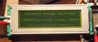 (Click on image above to see a bigger version).
This 240x64 pixel display is a unit with a parallel
interface to an onboard Toshiba T6963C graphics LCD controller. This is
connected to the SIgnal Labs development board using two ports, one for the 8-bit
bus to the module and the other for the handshake lines. I have configured the
software to communicate with the Toshiba controller using a bit banging
technique. I chose this approach because it is generally more portable to take
the same hook-up and supporting code and move it to a different processor
platform. It is also possible to connect the T6963C controller to the external
XRAM bus of a typical 8051/8052 derivative chip and use MOVX instructions to
communicate to the graphics module in that manner. The code supplied below can
be easily modified to support this mode of operation. The schematic below shows
the connections from the Port 2 and Port 3 headers of the Cygnal development
platform to the Optrex display. Note that the Optrex display is a device with a
5 volt power supply requirement and the pullup resistors on all the lines are
there to provide full 5 volt swings of the interface signals. The Silicon Labs
processor is quite happy with this mode of operation as it has I/Os that are 5V
tolerant.
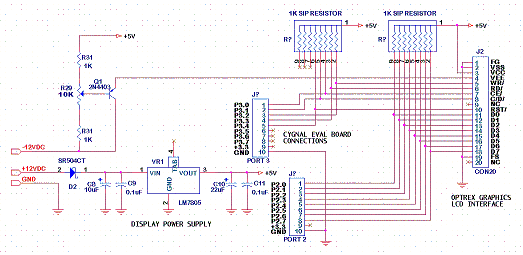 (Click on image above to see higher resolution
schematic).
This display is mapped to the memory buffer bytes
such that the bits in a specific byte are shown on the display as 8 horizontal
dots. Each line across the screen is made up of a string of these horizontal
bytes for a total of 30 bytes per line. There are a total of 64 lines of these
bytes. The part number of this display is Optrex America DMF-5005NY-LY-AKE
and they are available in stock at Digikey
under part number 73-1157-ND.
Download gLCD240x64.zip
(Please note that
I am providing this code "as-is" and it is up to you to determine its
usefulness for your application. As such you assume all responsibility for its
use and application. I cannot provide free technical support to help you get it
working for your controller or hardware setup. However if you have a minor question
of how some portion of the code works or why it was written in a particular way
please feel free to send me a question via email. I will try to answer all
questions but cannot guarantee this as I get tons of email and I also run a
consulting business to earn a living and that has to come first. You can also
email if you want support on a consulting basis. There is a link above with my
email address).


