 |
LCD Symbols
|
Using Special Symbols On Character Mode LCDs
Back To Embedded Info Page
The generic Hitachi type character mode LCD controllers support the loading of up to 8 user defined bitmaps into a page of onboard
character generator RAM known as the CGRAM. Many times it seems like the fact that only eight symbols are available is a severe limitation. On this
page I present a concept for an application that required more than 8 symbols for the application but was able to be supported by the display.
The application was one where an 8 column by 2 row (8x2) LCD display was to be used to show a display of the current settings of two parameters at the
same time. Each channel value could be set to values from 0.0 to 15.0. If a standard display scheme was used on this small 8x2 display using a decimal
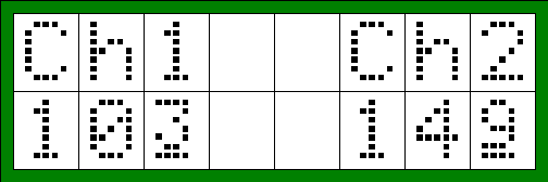
point to show the split at the end of the whole part of the number for Ch1=10.3 and Ch2=14.9 the display would look like this...

As you can see this just does not work well at all. So I devised a scheme to show the decimal part of the numbers with a smaller symbol with an underline. Using this scheme the above display would become......

This scheme requires a total of 10 special symbols, two more than the generic LCD display controller can accomodate if one were to think that all symbols needed to be loaded at once.
However you will notice that the display only requires at most two symbols to be loaded at any given time. So the concept used was to have the ten "soft symbols" defined as small font bitmaps in the code memory of the microcontroller. Then each time the display is painted the necessary two decimal digit symbols are loaded in real time to the display controller into CGRAM character locations #0 and #1.
Then when the second line of text on the display is painted the character code outputted for the third column is always 0x00 and the character code outputted for the eighth column is always 0x01.
For those that are interested here is the assembly language table of the bitmaps for the ten soft font symbols.
    dc.b    $0C,$12,$12,$12,$0C,$00,$1E,$00    ;4x5 Symbol 0
    dc.b    $08,$18,$08,$08,$1C,$00,$1E,$00    ;4x5 Symbol 1
    dc.b    $0C,$12,$04,$08,$1E,$00,$1E,$00    ;4x5 Symbol 2
    dc.b    $1E,$02,$1C,$02,$1C,$00,$1E,$00    ;4x5 Symbol 3
    dc.b    $14,$14,$14,$1E,$04,$00,$1E,$00    ;4x5 Symbol 4
    dc.b    $1E,$10,$1C,$02,$1C,$00,$1E,$00    ;4x5 Symbol 5
    dc.b    $0E,$10,$1C,$12,$0C,$00,$1E,$00    ;4x5 Symbol 6
    dc.b    $1E,$02,$04,$04,$04,$00,$1E,$00    ;4x5 Symbol 7
    dc.b    $0C,$12,$0C,$12,$0C,$00,$1E,$00    ;4x5 Symbol 8
    dc.b    $0C,$12,$0E,$02,$1C,$00,$1E,$00    ;4x5 Symbol 9
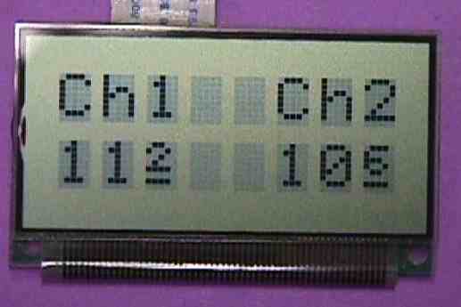
And finally, here is a photo of the actual display showing what it looks like close up in real life. Note that tbe bias voltage of the LCD was purposely set so that the blank pixels of the display would show up in the background of the photo.


