 |
SiLabs ICD
|
Using SiLabs' Onboard ICD In Target System
Back To Embedded Info Page
I took on a low budget project to make some changes to the 8051 firmware in an existing product that was designed about 12 years ago. In trying to decide how to support an environment that would permit me to change the 8051 code and then debug it I was faced with not wanting to purchase an expensive ICE unit. In addition, the development system utilized to produce the code originally was not available. So I solved this problem in a cost effective manner with a solution that utilized more of my time than my financal resources.
For $99 at Digikey I bought a SiLabs development board for their 'F2xx series 8051 derivative parts. This comes with an IDE and the Keil assembler, debugger, and a size limited C compiler. I also bought some of the 'F226 processors from Digikey (about $10 each) and a couple of connectors and a 12" Parlex flex cable that is 10 conductors wide all for about another $15). I used the connectors to make an adapter to connect from the SiLabs JTag Pod to my target where I needed a very small 10 pin debug connector and not the normal 2 by 5 ribbon header on 0.1" centers.
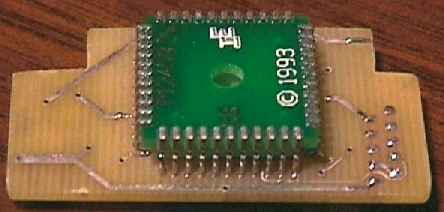
I then devised a small circuit board design to mount the SiLabs part, a regulator to convert the target socket 5V to 3.3V for the 'F226, a 10 pin flex connecor and a bunch of 10K pullup resistors. On the bottom side this adapter has a PLCC-44 foot that I bought from Ironwood Electronics that permits it to fit into an existing PLCC socket (PLCC foot at $35 and adapter PC boards 2 for $68 from Alberta Printed Circuits prototype P1 service).
I used the target hardware provided by the client as a test & debug support platform. I took the lower and upper boards and separated them and mounted them onto a small board that serves as a base. This setup was also changed so that it is powered from a wall adapter instead of the normal battery. I wired the lower board to the upper board with a piece of 6 conductor wire.
The picture below shows this initial configuration.
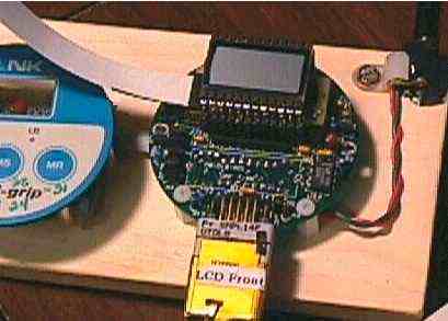
The adapter PC board that has the SiLabs in-circuit reprogrammable microcontroller on it with, its modern and up to date debugging and test features, is designed to fit right into the existing microcontroller PLCC-44 socket and adapt to the new microcontroller. This adapter permits me to connect the test platform to development software on my PC via a COMM port through the SiLabs RS232 <-> JTag converter pod.
Top View of the adapter:

Here is a bottom view of the adapter showing the PLCC-44 foot:
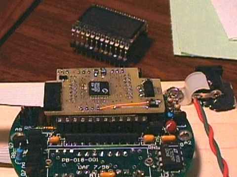
The completed adapter assembly is fitted into the PLCC socket of the target hardware. The following picture shows this configuration. Notice the flat flex cable attached from the left. This is the JTag cable, which I found out from a support person at SiLabs, can be as much as 15 inches long.
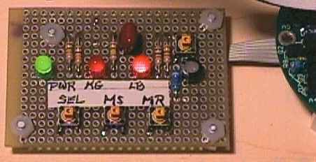
During the initial software work I found it extremely difficult to use the upper board assembly with its dome switches under a lexan overlay. During the software work it was necessary to press some of these switches literally dozens of times. For this reason I duplicated the equivalent functionality of the upper board assembly onto a small piece of prototype board using switches that are easy to operate and have a good tactile feedback. The following two pictures show a closeup of this additional assembly and how it connects to the microcontroller board.
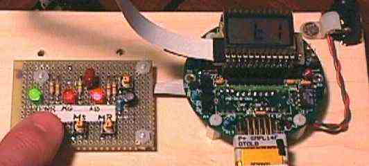
Once the adapter was completed I had to make the existing code work with it. Quite a bit of work was required to adapt the code. I also found that the existing code had some problems with the way the LCD display driver and the keyboard poller worked so I re-wrote parts of the code to solve these issues.
This solution has worked out well to give full debuggability to the software for the client product with some special considerations as follows:
- The original CPU was an Intel 8052 running at 4.9152 MHz.
- The design was one not using the external bus of the 8052 and also note that the SiLabs C8051F226 that I used also does not have an external bus but it does have 4 ports and the normal 8052 complement of peripherals.
- The SiLabs part has a divide by 1 from Xtal to the SYSCLK speed and not the /12 that the normal 8052 has.
- The SiLabs part puts the UART and EXT INTR 0 pins on the P0.0
-> P0.2 pins whereas the Intel had them on P3.0 -> P3.2. I swapped these connections in the design of the adapter.
The goal of course was to make an inexpensive yet effective debug platform!! I got that out of this effort but.... the source code must still be compiled to a target 87C52 to install in the client product. So the code base (which was not originally done by me but someone else back in 1991-1993) required more than a few tweaks to get it to a run in the SiLabs environment. Thus the code has a fair number of conditional compile statements like:
    #if SILABS_DEBUG

       . . . . do this for test platform

    #else

       . . . . do this for the target 8052

    #endif
I also had to re-design the code to get rid of all instances of
places where the intrinsic speed of the processor was used to produce intentional software delays. This was found in a generic Delay 1 mSec subroutine, a delay 10 mSec subroutine, and in an autobaud routine. I changed the code (the way one should do it anyway) to use a timer interrupt. Now this stuff works the same on both the test and target platforms !!
Regarding the SiLabs JTAG debugger and IDE... I found it quite useful for the project described above. That was a single source file of assembler that makes into about 5K of 8052 code. The editor function is quite adequate, but it is no CodeWrite. During debug mode there are a few things that could be easier to use....but then for $99 one can't ask for something like the $2000 Keil uVision2 IDE.
I think the SiLabs microcontroller on-board debug hardware is excellent. They support up to 4 hardware breakpoints and some number of watch points. These let the target microcontroller run at full tilt right from FLASH until a breakpoint is hit. The FLASH memory in the SiLabs part also has a substantial endurance life so there is no worry during the debug session how many times you re-compile and download new object code to the target processor.


